Introduction
As an introduction let us check some important terms used in this field.
Microcomputer
The term microcomputer is generally synonymous with a personal computer, or a computer that depends on a microprocessor. Microcomputers are designed to be used by individuals, whether in the form of PCs, workstations or notebook computers. A microcomputer contains a CPU on a microchip (the microprocessor), a memory system (typically ROM and RAM), a bus system and I/O ports, typically housed in a motherboard.
Microprocessor
A silicon chip that contains a CPU. In the world of personal computers, the terms microprocessor and CPU are used interchangeably.
A microprocessor (sometimes abbreviated µP) is a digital electronic component with miniaturized transistors on a single semiconductor integrated circuit (IC).
One or more microprocessors typically serve as a central processing unit (CPU) in a computer system or handheld device. Microprocessors made possible the advent of the microcomputer.
- At the heart of all personal computers and most working stations sits a microprocessor.
- Microprocessors also control the logic of almost all digital devices, from clock radios to fuel-injection systems for automobiles.
Three basic characteristics that differentiate microprocessors are given below
1. Instruction set
The set of instructions that the microprocessor can execute.
2. Bandwidth
The number of bits processed in a single instruction.
3. Clock speed
Given in megahertz (MHz), the clock speed determines how many instructions per second the processor can execute
In both cases, the higher the value, the more powerful the CPU. For example, a 32-bit microprocessor that runs at 50MHz is more powerful than a 16-bit microprocessor that runs at 25MHz.
In addition to bandwidth and clock speed, microprocessors are classified as being either RISC (reduced instruction set computer) or CISC (complex instruction set computer). (We will study CISC and RISC in more details).
Microcontroller
A highly integrated chip that contains all the components comprising a controller. Typically this includes a CPU, RAM, some form of ROM, I/O ports, and timers. Unlike a general-purpose computer, which also includes all of these components, a microcontroller is designed for a very specific task to control a particular system.
A microcontroller differs from a microprocessor, which is a general-purpose chip that is used to create a multi-function computer or device and requires multiple chips to handle various tasks.
A microcontroller is meant to be more self-contained and independent, and functions as a tiny, dedicated computer. The great advantage of microcontrollers, as opposed to using larger microprocessors, is that the parts-count and design costs of the item being controlled can be kept to a minimum.
They are typically designed using CMOS (complementary metal oxide semiconductor) technology, an efficient fabrication technique that uses less power and is more immune to power spikes than other techniques.
Microcontrollers are sometimes called embedded microcontrollers, which just means that they are part of an embedded system that is, one part of a larger device or system.
Microprocessor vs Microcontroller
Figure 1 shows the main difference between the microcontroller and microprocessor.

Figure : Blocks of a microcontroller and processor
A microprocessor requires an external memory for program/data storage. Instruction execution requires the movement of data from the external memory to the microprocessor or vice versa. Usually, microprocessors have good computing power and they have higher clock speed to facilitate faster computation.
A microcontroller has required on-chip memory with associated peripherals. A microcontroller can be thought of as a microprocessor with inbuilt peripherals.
A microcontroller does not require any additional interfacing ICs for operation and it functions as a standalone system. The operation of a microcontroller is multipurpose, just like a Swiss knife.
Microcontrollers are also called embedded controllers. A microcontroller clock speed is limited only to a few tens of MHz. Microcontrollers are numerous, and many of them are application specific.
Development / Classification of microcontrollers
Microcontrollers have gone through a silent revolution (invisible). The evolution can be rightly termed as silent as the impact or application of a microcontroller is not well known to a common user, although microcontroller technology has undergone significant change since the early 1970s. The development of some popular microcontrollers is given in Table 1.
Table : Size and release year of some popular microcontrollers
| Intel 4004 | 4 bit (2300 PMOS trans, 108 kHz) | 1971 |
| Intel 8048 | 8 bit | 1976 |
| Intel 8031 | 8 bit (ROM-less) | . |
| Intel 8051 | 8 bit (Mask ROM) | 1980 |
| Microchip PIC16C64 | 8 bit | 1985 |
| Motorola 68HC11 | 8bit (on-chip ADC) | . |
| Intel 80C196 | 16 bit | 1982 |
| Atmel AT89C51 | 8bit(Flash memory) | . |
| Microchip PIC 16F877 | 8bit (Flash memory + ADC) | . |
Development of microprocessors
Microprocessors have undergone significant evolution over the past four decades. This development is perceptible to a common user, especially, in terms of phenomenal growth in the capabilities of personal computers. The development of some of the microprocessors can be given in Table 2.
Table : List of Some popular microprocessors with size and year
| Intel 4004 | 4 bit (2300 PMOS transistors) | 1971 |
Intel 8080 8085 | 8-bit (NMOS) 8 bit | 1974 |
Intel 8088 8086 | 16-bit 16 bit | 1978 |
Intel 80186 80286 | 16 bit 16 bit | 1982 |
| Intel 80386 | 32 bit (275000 transistors) | 1985 |
Intel 80486 SX DX | 32 bit 32 bit (built in floating point unit) | 1989 |
| Intel 80586 I MMX Celeron II III IV | 64 bit | 1993 1997 1999 2000 |
| Z-80 (Zilog) | 8 bit | 1976 |
| Motorola Power PC 601 602 603 | 32-bit | 1993 1995 |
Embedded system
An embedded system is a combination of computer hardware and software designed for a specific function.
Embedded system categories
Embedded systems can also be categorized by their performance requirements:
Small-scale embedded systems often use no more than an 8-bit microcontroller.
Medium-scale embedded systems use a larger microcontroller (16-32 bit) and often link microcontrollers together.
Sophisticated-scale embedded systems often use several algorithms that result in software and hardware complexities and may require more complex software, a configurable processor and/or a programmable logic array.
Examples of embedded systems
Embedded systems are used in a wide range of technologies across an array of industries. Some examples include:
Automobiles.
Modern cars commonly consist of many computers (sometimes as many as 100), or embedded systems, designed to perform different tasks within the vehicle. Some of these systems perform basic utility functions and others provide entertainment or user-facing functions. Some embedded systems in consumer vehicles include cruise control, backup sensors, suspension control, navigation systems and airbag systems.
Mobile phones
These consist of many embedded systems, including GUI software and hardware, operating systems (OSes), cameras, microphones, and USB (Universal Serial Bus) I/O (input/output) modules.
Industrial machines
They can contain embedded systems, like sensors, and can be embedded systems themselves. Industrial machines often have embedded automation systems that perform specific monitoring and control functions.
Medical equipment
These may contain embedded systems like sensors and control mechanisms. Medical equipment, such as industrial machines, also must be very user-friendly so that human health isn’t jeopardized by preventable machine mistakes. This means they’ll often include a more complex OS and GUI designed for an appropriate UI.
The Bus
Introduction
A computer system consists of three major components: a processor, a memory unit, and an input/output (I/O) subsystem. An interconnection network facilitates communication among these three components, which is called a bus. The term “bus” is used to represent a group of electrical signals or the wires that carry these signals.
System bus Components
The system bus consists of three major components: an address bus, a data bus, and a control bus.
The address bus width determines the amount of physical memory addressable by the processor.
The data bus width indicates the size of the data transferred between the processor and memory or an I/O device.
For example, the Pentium processor (We will study it later) has 32 address lines and 64 data lines. Thus, the Pentium can address up to 232, or 4 GB of memory. Furthermore, each data transfer can move 64 bits of data.
The control bus consists of a set of control signals. Typical control signals include memory read, memory writes, I/O read, I/O write, interrupt, interrupt acknowledge, bus request, and bus grant. These control signals indicate the type of action taking place on the system bus.
For example, when the processor is writing data into the memory, the memory writes signal is generated. Similarly, when the processor is reading from an I/O device, it generates the I/O read signal. A bus connects various components in a computer system.
Bus Categories
Thus buses can be categorised into
Internal buses: The processor uses several internal buses to interconnect registers and the ALU.
External buses: are used to interface with the devices outside a typical processor system. By our classification, serial and parallel interfaces, Universal Serial Bus (USB). These buses are typically used to connect I/O devices.
Bus multiplexing
One problem with the dedicated bus design is that it requires a large number of wires. We can reduce this count by using multiplexed buses.
For example, a single bus may be used for both address and data.
In addition, the address and data bus widths play an important role in determining the address space and data transfer rate, respectively.
Bus Parameters
Bus Width
Bus width refers to the data and address bus widths. System performance improves with a wider data bus as we can move more bytes in parallel. We increase the addressing capacity of the system by adding more address lines.
Bus Type
As discussed in the last section, there are two basic types of buses: dedicated and multiplexed.
Bus Operations
Bus systems support several types of operations to transfer data. These include the read, write, block transfer, read-modify-write, and interrupt.
Bus structure
Figure 2 and Figure 3 represent the block diagram of a typical single bus and double bus architecture. Table 3 shows the differences between a single bus structure and a double bus structure.
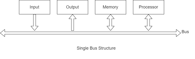
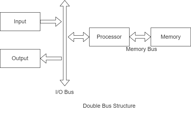
Table : Difference between single and double bus structures 
Introduction to 8085
8085 is pronounced as “eighty-eighty-five” microprocessor. It is an 8-bit microprocessor designed by Intel in 1977 using NMOS technology.
It has the following configuration
- 8-bit data bus
- 16-bit address bus, which can address up to 64KB
- A 16-bit program counter, A 16-bit stack pointer
- Six 8-bit registers arranged in pairs: BC, DE, HL
- Requires +5V supply to operate at 3.2 MHZ single phase clock
Architecture of 8085
Figure 4 shows the architecture of the 8085 microprocessor. Details of each functional block are explained below. From an exam point of view, this is a very important topic.

Figure : 8085 microcontroller architecture
Arithmetic and logic unit (ALU)
As the name suggests, it performs arithmetic and logical operations like Addition, Subtraction, AND, OR, etc. on 8-bit data.
Accumulator
It is an 8-bit register used to perform arithmetic, logical, I/O & LOAD/STORE operations. It is connected to the internal data bus & ALU.
General purpose register
There are 6 general purpose registers in the 8085 processor, i.e. B, C, D, E, H &L. Each register can hold 8-bit data. These registers can work in pairs to hold 16-bit data and their pairing combination is like B-C, D-E & H-L.
Program counter
It is a 16-bit register used to store the memory address location of the next instruction to be executed.
The microprocessor increments the program whenever an instruction is being executed so that the program counterpoints to the memory address of the next instruction that is going to be executed.
Stack pointer
It is also a 16-bit register that works like a stack, which is always incremented/decremented by 2 during PUSH & POP operations.
Temporary register
It is an 8-bit register, which holds the temporary data of arithmetic and logical operations.
Flag register
It is an 8-bit register having five 1-bit flip-flops, which hold either 0 or 1 depending upon the result stored in the accumulator.
The bit positions of the flags are shown in Figure 5.

These are the set of 5 flip-flops and they are listed below.
Sign (S)
If the result of an MSB operation is 1 then it is set else it is reset.
Zero (Z)
Set if the result of an instruction is zero.
Auxiliary Carry (AC)
This flag is set to a 1 by the instruction just ending if a carry occurred from bit 3 to bit 4 of the accumulator during the instruction’s execution. Because of the relationships of decimal in pure BCD to hexadecimal coding, it is possible to bring BCD values directly into the A Register and perform mathematical operations on them. The result, however, will be as if two hex characters are being processed. If the result must be returned to the program as BCD rather than as hex, the Decimal Adjust Accumulator (DAA) instruction can make that translation; the Auxiliary Carry Flag is provided to assist in this operation.
Parity (P)
The parity flag is used for results containing an even number of ones. This may be useful in I/O operations with serial devices, or any place where error checking is to be done.
Carry (C)
The carry flag is used for carrying and borrowing in case of addition and subtraction operations.
Instruction register and decoder
It is an 8-bit register. When an instruction is fetched from memory then it is stored in the Instruction register. The instruction decoder decodes the information present in the Instruction register.
Timing and control unit
It provides a timing and control signal to the microprocessor to perform operations.
Following are the timing and control signals, which control external and internal circuits:
- Control Signals: READY,, , ALE
- Status Signals: S0, S1,
- DMA Signals: HOLD, HLDA
- RESET Signals: RESET IN, RESET OUT
Interrupt control
As the name suggests it controls the interrupts during a process. When a microprocessor is executing the main program and whenever an interrupt occurs, the microprocessor shifts the control from the main program to process the incoming request. After the request is completed, the control goes back to the main program.
There are 5 interrupt signals in the 8085 microprocessor and they are INTR, RST 7.5, RST 6.5, RST 5.5, and TRAP.
Serial Input/output control
It controls serial data communication by using these two instructions: SID (Serial input data) and SOD (Serial output data).
Address buffer and address-data buffer
The content stored in the stack pointer and program counter is loaded into the address buffer and address-data buffer to communicate with the CPU. The memory and I/O chips are connected to these buses; the CPU can exchange the desired data with the memory and I/O chips.
Address bus and data bus
Data bus carries the data to be stored. It is bidirectional, whereas the address bus carries the location to where it should be stored and it is unidirectional. It is used to transfer the data & Address I/O devices.
8085 Buses
A typical system uses several buses, a collection of wires, which transmit binary numbers, one bit per wire. A typical microprocessor communicates with memory and other devices (input and output) using three buses: Address Bus, Data Bus and Control Bus.
Address Bus
The Address Bus consists of 16 wires, therefore Its “width” is 16 bits. A 16-bit Address bus can identify memory locations i.e. 0000000000000000 up to 1111111111111111. Because memory consists of boxes, each with a unique address, the size of the address bus determines the size of memory, which can be used. To communicate with memory the microprocessor sends an address on the address bus, e.g. 0000000000000011 (3 in decimal), to the memory. The memory selects box number 3 for reading or writing data. The address bus is unidirectional.